CS274: Computer Architecture - MIPS Processor Design: The ALU
Activity Goals
The goals of this activity are:
- To incorporate the design of a 1-bit adder into a 1-bit ALU
- To combine 1-bit ALUs into a 32-bit ALU design
- To support subtraction within a 32-bit adder
- To enable status bits to support the MIPS isntruction set from an ALU
- To optimize an ALU for performance using a Carry Lookahead Adder
The Activity
Directions
Consider the activity models and answer the questions provided. First reflect on these questions on your own briefly, before discussing and comparing your thoughts with your group. Appoint one member of your group to discuss your findings with the class, and the rest of the group should help that member prepare their response. Answer each question individually from the activity, and compare with your group to prepare for our whole-class discussion. After class, think about the questions in the reflective prompt and respond to those individually in your notebook. Report out on areas of disagreement or items for which you and your group identified alternative approaches. Write down and report out questions you encountered along the way for group discussion.
Model 1: Review: Components for a 1-bit Adder

sum = (A xor B) xor carryIn
carryOut = ((A xor B) and carryIn) or (A and B)
| A |
B |
Sum |
Carry |
| 0 |
0 |
0 |
0 |
| 0 |
1 |
1 |
0 |
| 1 |
0 |
1 |
0 |
| 1 |
1 |
0 |
1 |
Questions
- Draw a 1-bit adder using these logic formulas
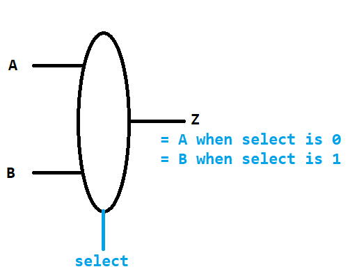
Model 2: A Multiplexor Circuit
| A |
B |
select |
Z |
| 0 |
0 |
0 |
0 |
| 0 |
0 |
1 |
0 |
| 0 |
1 |
0 |
0 |
| 0 |
1 |
1 |
1 |
| 1 |
0 |
0 |
1 |
| 1 |
0 |
1 |
0 |
| 1 |
1 |
0 |
1 |
| 1 |
1 |
1 |
1 |
Questions
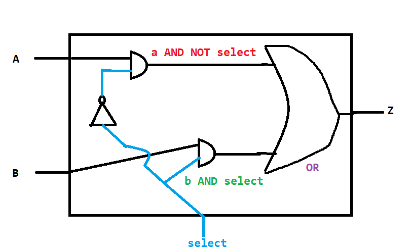
- The multiplexor (or "mux") takes two inputs and selects one of them: for example,
A passes through if select is 0, and B passes through if select is 1. Draw a truth table and circuit for an ALU that selects between four options (you will need two select bits).
Model 3: A 1-bit ALU
Questions
- Add the select line to this ALU such that the AND operation is select bits 00, the OR operation is select bits 01, and the adder is select bits 10. Call this select line
operation.
Model 4: A 32-bit ALU
Questions
- Suppose you had an 8-bit ALU. Connect each of the 8-bits of the inputs
A and B to 8 individual ALUs. Where would you connect the select operation lines, and the carry inputs and outputs? Sketch your final result.
Model 5: Subtraction
Questions
- Recall that binary subtraction involves adding the two's-complement inverse of
B to A. Modify your 1-bit ALU design to invert B, and select either it or the original B value using a multiplexor. You can call your new select input bInvert.
- However, you must also add 1 to the final answer to perform the two's complement. How can you use the existing 32-bit ALU design to add 1 in the one's place?
Model 6: Overflow Detection
| MSB |
|
|
|
|
|
|
|
|
| carryIn |
0 |
0 |
0 |
0 |
1 |
1 |
1 |
1 |
| A |
0 |
0 |
1 |
1 |
0 |
0 |
1 |
1 |
| B |
0 |
1 |
0 |
1 |
0 |
1 |
0 |
1 |
| sum |
0 |
1 |
1 |
0 |
1 |
0 |
0 |
1 |
| carryOut |
0 |
0 |
0 |
1 |
0 |
1 |
1 |
1 |
| A sign? |
+ |
+ |
- |
- |
+ |
+ |
- |
- |
| B sign? |
+ |
- |
+ |
- |
+ |
- |
+ |
- |
| sum sign? |
+ |
- |
- |
+ |
- |
+ |
+ |
- |
| Overflow? |
No |
No |
No |
Yes |
Yes |
No |
No |
No |
Questions
- Can overflow occur when adding values of different signs? Why or why not?
- For the cases where overflow occurs, what do their inputs and outputs have in common?
- Look again at the cases where overflow does not occur. How do the carry bits ultimately indicate whether overflow will or will not occur?
- Draw a truth table and circuit diagram using only the most significant carry in and out bits to indicate overflow detection.
Model 7: Status Bits (Zero and Less)
Questions
- If you are performing subtraction, what will you know about
B compared to A if the result is negative?
- Add a status line called
less to the output of the most significant bit ALU.
- What does overflow do to the sign bit of the output? If overflow occurs, can we fix the less bit output, and how?
- Draw a truth table with the less bit, overflow bit, and resulting "correct" less output. What circuit is this? Add it to your ALU!
- What circuit can tell you if all 32 bits of the ALU result line are 0? Add an ALU output called
zero that is set to 1 when this occurs. Hint - add a logic circuit that indicates if any of the bits is 1, and then negate it.
Model 8: Parallelized Addition with the Carry Lookahead Adder

| A |
B |
Carry State |
Logic formula |
| 0 |
0 |
kill |
A NOR B |
| 0 |
1 |
propagate |
A XOR B |
| 1 |
0 |
propagate |
A XOR B |
| 1 |
1 |
generate |
A AND B |
Questions
- What carry out bit is always generated if both
A and B are 1?
- What carry out bit is always generated if both
A and B are 0?
- What should the carry out bit be if
A and B are different?
- Write a logic formula for the carry out bit based on the carry in, generate, and propagate detection bits.
- Sketch a "carry lookahead" circuit that outputs all 32 carry bits.
- Design an ALU that adds all 32 bits in parallel using this carry lookahead circuit.
Submission
I encourage you to submit your answers to the questions (and ask your own questions!) using the Class Activity Questions discussion board. You may also respond to questions or comments made by others, or ask follow-up questions there. Answer any reflective prompt questions in the Reflective Journal section of your OneNote Classroom personal section. You can find the link to the class notebook on the syllabus.