CS274: Computer Architecture - 1 Bit ALU Design (100 Points)
Contents
Assignment Goals
The goals of this assignment are:
- To synthesize an adder and classic logic gates into a 1-bit ALU
Background Reading and References
Please refer to the following readings and examples offering templates to help get you started:
The Assignment
What to Do
Create a 1-bit ALU
Using the adder circuit from the prior lab, create a 1-bit ALU by creating and wiring the following additional components:
- Create and test a 3-bit and gate, and a 4-bit or gate
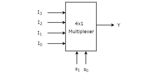
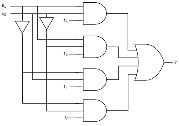
- Create and test a 4-to-1 multiplexor according to the design below. You will create four input pins (
I0,I1,I2, andI3), one select input (s: a 2-bitstd_logic_vector), and an output pin. Create four internal signals (sig1,sig2,sig3, andsig4) to hold the intermediate values. You can port map four and gates to signals like this:signal not_s0, not_s1 : std_logic; ... not_s0 <= not s(0); not_s1 <= not s(1); A1: and3 port map(w => I0, x => not_s0, y => not_s1, z => sig1);Using these and gates, allow
I0to pass whensis10,I1whensis01, and so on. If a bit ofsis0, invert it to produce a1. Finally, You canortogether the four internal signals, and wire that to the output pin, to complete the multiplexor. Note that if you only need fewer than 4 inputs to your multiplexor (say, one for the adder, one for theandgate, and one for theorgate), you can simply wireI0,I1, andI2to those pins or signals, and then create a placeholder signal that you can wire toI3. This will leave that pin essentially disconnected, or "floating". In other words, you can port mapI3to'0'.
- Create a structural ALU component that wires together a 2-bit and gate, a 2-bit or gate, and a full adder, and then multiplexes them together according to a select input, as shown in this design:

Your ALU will include an input calledALUOp, which is astd_logic_vector(1 downto 0). You will wire this to the select input of the mux to choose which operation your ALU will perform!
When finished with this base design, make the following modification.
Subtraction
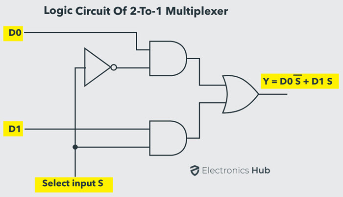
- Create and test a 2-to-1 multiplexor according to this design (note that your select input will only be 1 bit now!):
- Add a
bInvertinput bit to your design, and multiplex the input signalbwithnot b(using a 2-input mux), and use the resulting mux output as a signal to the remainingbinputs.
Testing
Here is an example testbench for the 1-bit ALU (you may need to change the labels to match the ones you used). It’s a good idea to also assert the values of the flag signals like zero, less, and overflow, which is left as an exercise for you. One pitfall to know about before you name your own ports: select is a reserved word in VHDL (it’s used by the with ... select statement), so you can’t use it as a port name — that’s why the operation-select port below is named op instead. If you ever get a mysterious syntax error on a line that looks fine, check whether you’ve accidentally used a reserved word (select, in, out, signal, …) as a name.
library ieee;
use ieee.std_logic_1164.all;

entity alu1bit_tb is
end alu1bit_tb;

architecture behavior of alu1bit_tb is
    component alu1bit
    port (
        a        : in  std_logic;
        b        : in  std_logic;
        carryin  : in  std_logic;
        bInvert  : in  std_logic;
        op       : in  std_logic_vector(1 downto 0);
        z        : out std_logic;
        carryout : out std_logic;
        zero     : out std_logic;
        less     : out std_logic;
        overflow : out std_logic
    );
    end component;

    signal ta, tb, tcarryin, tbInvert : std_logic;
    signal tselect : std_logic_vector(1 downto 0);
    signal tz, tcarryout, tzero, tless, toverflow : std_logic;
begin
    uut: alu1bit port map (
        a        => ta,
        b        => tb,
        carryin  => tcarryin,
        bInvert  => tbInvert,
        op       => tselect,
        z        => tz,
        carryout => tcarryout,
        zero     => tzero,
        less     => tless,
        overflow => toverflow
    );

    tb_proc: process
    begin
        -- Test ADD (select = "00", bInvert = '0')
        tselect <= "00"; tbInvert <= '0';

        ta <= '0'; tb <= '0'; tcarryin <= '0'; wait for 30 ns; assert tz = '0' report "ADD 0+0+0 failed";
        ta <= '0'; tb <= '0'; tcarryin <= '1'; wait for 30 ns; assert tz = '1' report "ADD 0+0+1 failed";
        ta <= '0'; tb <= '1'; tcarryin <= '0'; wait for 30 ns; assert tz = '1' report "ADD 0+1+0 failed";
        ta <= '0'; tb <= '1'; tcarryin <= '1'; wait for 30 ns; assert tz = '0' report "ADD 0+1+1 failed";
        ta <= '1'; tb <= '0'; tcarryin <= '0'; wait for 30 ns; assert tz = '1' report "ADD 1+0+0 failed";
        ta <= '1'; tb <= '0'; tcarryin <= '1'; wait for 30 ns; assert tz = '0' report "ADD 1+0+1 failed";
        ta <= '1'; tb <= '1'; tcarryin <= '0'; wait for 30 ns; assert tz = '0' report "ADD 1+1+0 failed";
        ta <= '1'; tb <= '1'; tcarryin <= '1'; wait for 30 ns; assert tz = '1' report "ADD 1+1+1 failed";

        -- Test SUBTRACT (select = "00", bInvert = '1')
        tselect <= "00"; tbInvert <= '1';

        ta <= '0'; tb <= '0'; tcarryin <= '1'; wait for 30 ns; assert tz = '0' report "SUB 0-0 failed";
        ta <= '0'; tb <= '1'; tcarryin <= '1'; wait for 30 ns; assert tz = '1' report "SUB 0-1 failed";
        ta <= '1'; tb <= '0'; tcarryin <= '1'; wait for 30 ns; assert tz = '1' report "SUB 1-0 failed";
        ta <= '1'; tb <= '1'; tcarryin <= '1'; wait for 30 ns; assert tz = '0' report "SUB 1-1 failed";

        -- Test AND (select = "01", bInvert irrelevant)
        tselect <= "01"; tbInvert <= '0';
        tcarryin <= '0'; -- carryin not used for AND

        ta <= '0'; tb <= '0'; wait for 30 ns; assert tz = '0' report "AND 0&0 failed";
        ta <= '0'; tb <= '1'; wait for 30 ns; assert tz = '0' report "AND 0&1 failed";
        ta <= '1'; tb <= '0'; wait for 30 ns; assert tz = '0' report "AND 1&0 failed";
        ta <= '1'; tb <= '1'; wait for 30 ns; assert tz = '1' report "AND 1&1 failed";

        -- Test OR (select = "10", bInvert irrelevant)
        tselect <= "10"; tbInvert <= '0';
        tcarryin <= '0'; -- carryin not used for OR

        ta <= '0'; tb <= '0'; wait for 30 ns; assert tz = '0' report "OR 0|0 failed";
        ta <= '0'; tb <= '1'; wait for 30 ns; assert tz = '1' report "OR 0|1 failed";
        ta <= '1'; tb <= '0'; wait for 30 ns; assert tz = '1' report "OR 1|0 failed";
        ta <= '1'; tb <= '1'; wait for 30 ns; assert tz = '1' report "OR 1|1 failed";

        report "Testbench finished successfully";
        wait;
    end process;
end behavior;
Test Bench Walkthrough
If this testbench looks intimidating, don’t worry — it follows the exact same recipe as the and2 testbench from the adder lab, just with more wires. Let’s walk through it piece by piece:
entity alu1bit_tb is ... end alu1bit_tb;— the testbench entity has no ports at all. That’s on purpose: a testbench isn’t a circuit that anyone else wires into; it’s the “outside world” that pokes at your circuit. All of its wiring is internal.component alu1bit ... end component;— this component declaration is a copy of the port list of the unit under test. Think of it as a forward declaration (like a function prototype in C): it tells the compiler “an entity namedalu1bitwith these exact ports exists in the work library.” The port names and types here must match youralu1bitentity exactly, or elaboration will fail.- The
signaldeclarations — one local signal per port of the ALU. Signals are the testbench’s “wires”:taandtbare wires we will drive with test values into the ALU’saandbinputs;tcarryin,tbInvert, andtselectdrive the control inputs; andtz,tcarryout,tzero,tless, andtoverfloware wires we attach to the ALU’s outputs so we can observe andasserton them. You can’t assign a value directly to a component’s port — you can only connect a wire to it — which is why every port gets a signal. (Thetprefix is just a naming convention meaning “test”; it also keeps the signal names from colliding with the port names.) uut: alu1bit port map (a => ta, b => tb, ...);— this instantiates one copy of your ALU (traditionally labeleduutfor “unit under test”) and wires it up. This is a named-association port map: on the left of each=>is the formal port name of the component (a,b,carryin, …), and on the right is the local signal (the wire) you’re connecting to that port (ta,tb,tcarryin, …). Reada => taas “connect portato wireta.” Because each connection is spelled out by name, the order of the lines doesn’t matter — you could listz => tzfirst and it would work identically. Contrast this with positional association,port map (ta, tb, tcarryin, ...), where the signals are matched to ports purely by position in the list: it’s shorter, but one misordered signal silently wires your circuit wrong. With ten ports, always use named association.- The stimulus process (
tb_proc: process ... end process;) — this is the script that runs the test. Each test line does three things: assign values to the input wires (ta <= '0'; tb <= '1'; ...), thenwait for 30 nsto give the simulated hardware time to react — remember, every gate in your design has a 2 ns propagation delay, and the signal has to ripple through several gates (mux, adder, mux again), so we wait comfortably longer than the total delay before looking at the output — and thenassertthat the output wire has the expected value, with areportmessage that is printed only if the assertion fails. Silence means passing. - The final
wait;— a process in VHDL restarts from the top forever, like an infinite loop. A barewait;(with no time or condition) suspends the process permanently, so the tests run exactly once and the simulation ends instead of looping through the test cases for all eternity.
One historical note: an earlier version of this testbench used select as the port name and declared signals carryin/bInvert while port-mapping tcarryin/tbInvert — two bugs that GHDL happily reports as errors. The listing above fixes both, but they’re exactly the kinds of mistakes you’ll make yourself, so it’s worth recognizing the error messages now: a reserved word used as an identifier produces a confusing syntax error on the port declaration, while a signal-name mismatch produces a “no declaration for tcarryin” style error at the port map.
Deriving the Flag Outputs
Your ALU reports four status flags alongside its result. Here’s where each one comes from, and why.
Overflow: carryIn xor carryOut of the most-significant bit
In two’s complement arithmetic, overflow means the true mathematical result doesn’t fit in the available bits — e.g., adding two positive numbers and getting a “negative” bit pattern. The elegant hardware test: overflow occurred exactly when the carry into the sign (most-significant) bit differs from the carry out of it.
Why does that work? The sign bit is special: a carry into it changes the apparent sign of the result, while a carry out of it just falls off the end. If both happen (or neither happens), their effects on the sign are consistent with ordinary arithmetic and the answer is correct. If exactly one happens, the sign bit was corrupted — that’s overflow. Hence xor:
| carryIn (to MSB) | carryOut (of MSB) | overflow | 1-bit example (a + b + carryIn at the MSB position) |
|---|---|---|---|
| 0 | 0 | 0 | 0 + 0 + 0 = 0, no carry anywhere — fine |
| 0 | 1 | 1 | 1 + 1 + 0 = 10: carry out but no carry in — sign corrupted |
| 1 | 0 | 1 | 0 + 0 + 1 = 1: carry in but no carry out — sign corrupted |
| 1 | 1 | 0 | 1 + 1 + 1 = 11: carry in and carry out — consistent, fine |
Worked 4-bit example: 0111 + 0001 (that is, 7 + 1). The low three bits generate a carry chain, so the carry into the MSB is 1; but 0 + 0 + 1 = 1 at the MSB produces no carry out (carryOut = 0). 1 xor 0 = 1: overflow! And indeed, the result 1000 reads as −8 in two’s complement — 7 + 1 does not equal −8, so the flag is right.
For your 1-bit ALU, the “most significant bit” is the only bit, so overflow <= carryin xor carryout — but expose it as a pin now so that the 4-bit ALU lab can take it from the top slice.
Zero: NOR of all result bits
The result is zero exactly when no result bit is a 1. or is the “is any input 1?” detector: OR-ing all the result bits together yields 1 if any bit is set, and 0 only when every bit is 0. Inverting that gives the zero flag: zero <= not (all result bits or'd together) — a NOR. For the 1-bit ALU this collapses to zero <= not z, but build the habit now: for 4 bits it becomes not (r(3) or r(2) or r(1) or r(0)).
| result (4-bit example) | OR of bits | zero |
|---|---|---|
0000 |
0 | 1 |
0001 |
1 | 0 |
1000 |
1 | 0 |
Negative / less: the MSB of the result
In two’s complement, the most-significant bit is the sign bit: 1 means negative. So the “negative” (or less, as in “a − b < 0”) flag is simply the MSB of the result — for the 1-bit ALU, less <= z (from the subtraction result). For example, computing 3 − 5 in 4 bits gives 0011 + 1010 + 1 = 1110 (−2): MSB is 1, so less = 1, correctly telling us 3 < 5.
Carry-out: the adder’s final carry
carryout is just the carry output of your (most significant) full adder, passed straight through to a pin. Don’t confuse it with overflow — they answer different questions. Carry-out signals that the result doesn’t fit as an unsigned number; overflow signals that it doesn’t fit as a signed (two’s complement) number. They can disagree in both directions:
1111 + 0001 = (1)0000— carryout = 1 (unsigned 15 + 1 = 16 doesn’t fit), but overflow = 0 (signed: −1 + 1 = 0, which is exactly right — carry into MSB and carry out of MSB are both 1).0111 + 0001 = 1000— carryout = 0, but overflow = 1 (signed 7 + 1 ≠ −8, as we saw above).
Asserting the Flags in Your Testbench
When you extend the testbench, don’t just check tz — explicitly assert the flag outputs too, in the same style as the existing test lines. Here are a few examples you can adapt (add them right after a wait for 30 ns so the flags have settled):
-- After SUB 1-1 (result should be 0): the zero flag should be set
ta <= '1'; tb <= '1'; tcarryin <= '1'; tbInvert <= '1'; tselect <= "00";
wait for 30 ns;
assert tzero = '1' report "zero flag not set for 1-1";

-- After SUB 0-1 (result is negative): the less flag should be set
ta <= '0'; tb <= '1'; tcarryin <= '1'; tbInvert <= '1'; tselect <= "00";
wait for 30 ns;
assert tless = '1' report "less flag not set for 0-1";

-- ADD 1+1: carry in (0) differs from carry out (1), so overflow should be set
ta <= '1'; tb <= '1'; tcarryin <= '0'; tbInvert <= '0'; tselect <= "00";
wait for 30 ns;
assert toverflow = '1' report "overflow flag not set for 1+1";
Submission
In your submission, please include answers to any questions asked on the assignment page, as well as the questions listed below, in your README file.
If you wrote code as part of this assignment, please describe your design, approach, and implementation in a separate document prepared using a word processor or typesetting program such as LaTeX. This document should include specific instructions on how to build and run your code, and a description of each code module or function that you created suitable for re-use by a colleague.
In your README, please include answers to the following questions:
- Describe what you did, how you did it, what challenges you encountered, and how you solved them.
- Please answer any questions found throughout the narrative of this assignment.
- If collaboration with a buddy was permitted, did you work with a buddy on this assignment? If so, who? If not, do you certify that this submission represents your own original work?
- Please identify any and all portions of your submission that were not originally written by you (for example, code originally written by your buddy, or anything taken or adapted from a non-classroom resource). It is always OK to use your textbook and instructor notes; however, you are certifying that any portions not designated as coming from an outside person or source are your own original work.
- Approximately how many hours it took you to finish this assignment (I will not judge you for this at all...I am simply using it to gauge if the assignments are too easy or hard)?
- Your overall impression of the assignment. Did you love it, hate it, or were you neutral? One word answers are fine, but if you have any suggestions for the future let me know.
- Using the grading specifications on this page, discuss briefly the grade you would give yourself and why. Discuss each item in the grading specification.
- Any other concerns that you have. For instance, if you have a bug that you were unable to solve but you made progress, write that here. The more you articulate the problem the more partial credit you will receive (it is fine to leave this blank).
- Please describe any use of outside resources you may have engaged in the completion of this assignment, including the use of generative Artificial Intelligence.
Assignment Rubric
| Description | Pre-Emerging (< 50%) | Beginning (50%) | Progressing (85%) | Proficient (100%) |
|---|---|---|---|---|
| Algorithm Implementation (60%) | The algorithm fails on the test inputs due to major issues, or the program fails to compile and/or run | The algorithm fails on the test inputs due to one or more minor issues | The algorithm is implemented to solve the problem correctly according to given test inputs, but would fail if executed in a general case due to a minor issue or omission in the algorithm design or implementation | A reasonable algorithm is implemented to solve the problem which correctly solves the problem according to the given test inputs, and would be reasonably expected to solve the problem in the general case |
| Code Quality and Documentation (30%) | Code commenting and structure are absent, or code structure departs significantly from best practice, and/or the code departs significantly from the style guide | Code commenting and structure is limited in ways that reduce the readability of the program, and/or there are minor departures from the style guide | Code documentation is present that re-states the explicit code definitions, and/or code is written that mostly adheres to the style guide | Code is documented at non-trivial points in a manner that enhances the readability of the program, and code is written according to the style guide |
| Writeup and Submission (10%) | An incomplete submission is provided | The program is submitted, but not according to the directions in one or more ways (for example, because it is lacking a readme writeup) | The program is submitted according to the directions with a minor omission or correction needed, and with at least superficial responses to the bolded questions throughout | The program is submitted according to the directions, including a readme writeup describing the solution, and thoughtful answers to the bolded questions throughout |
Please refer to the Style Guide for code quality examples and guidelines.